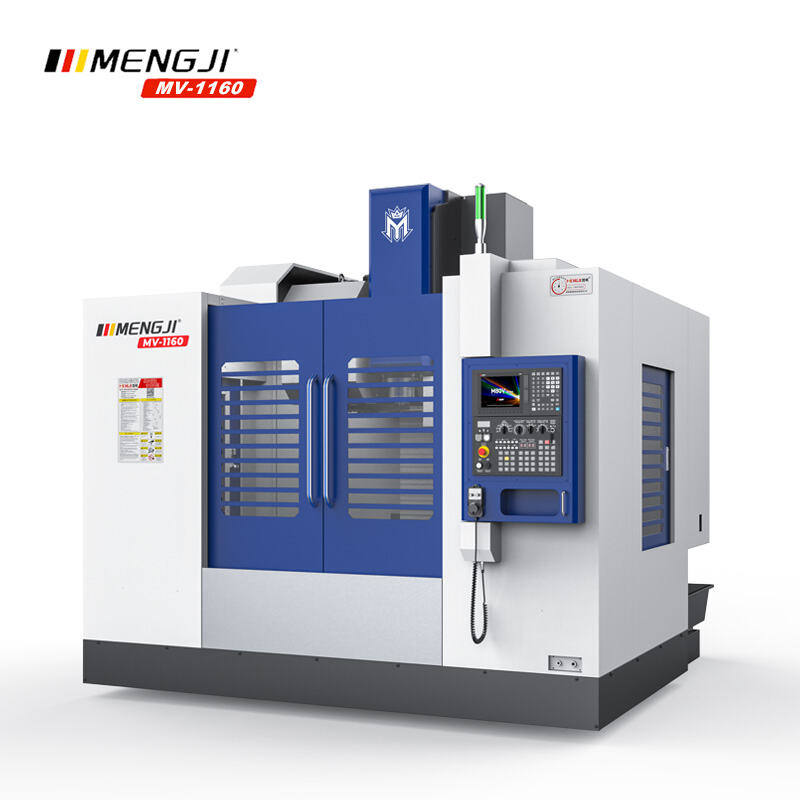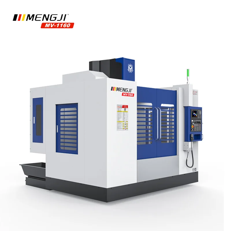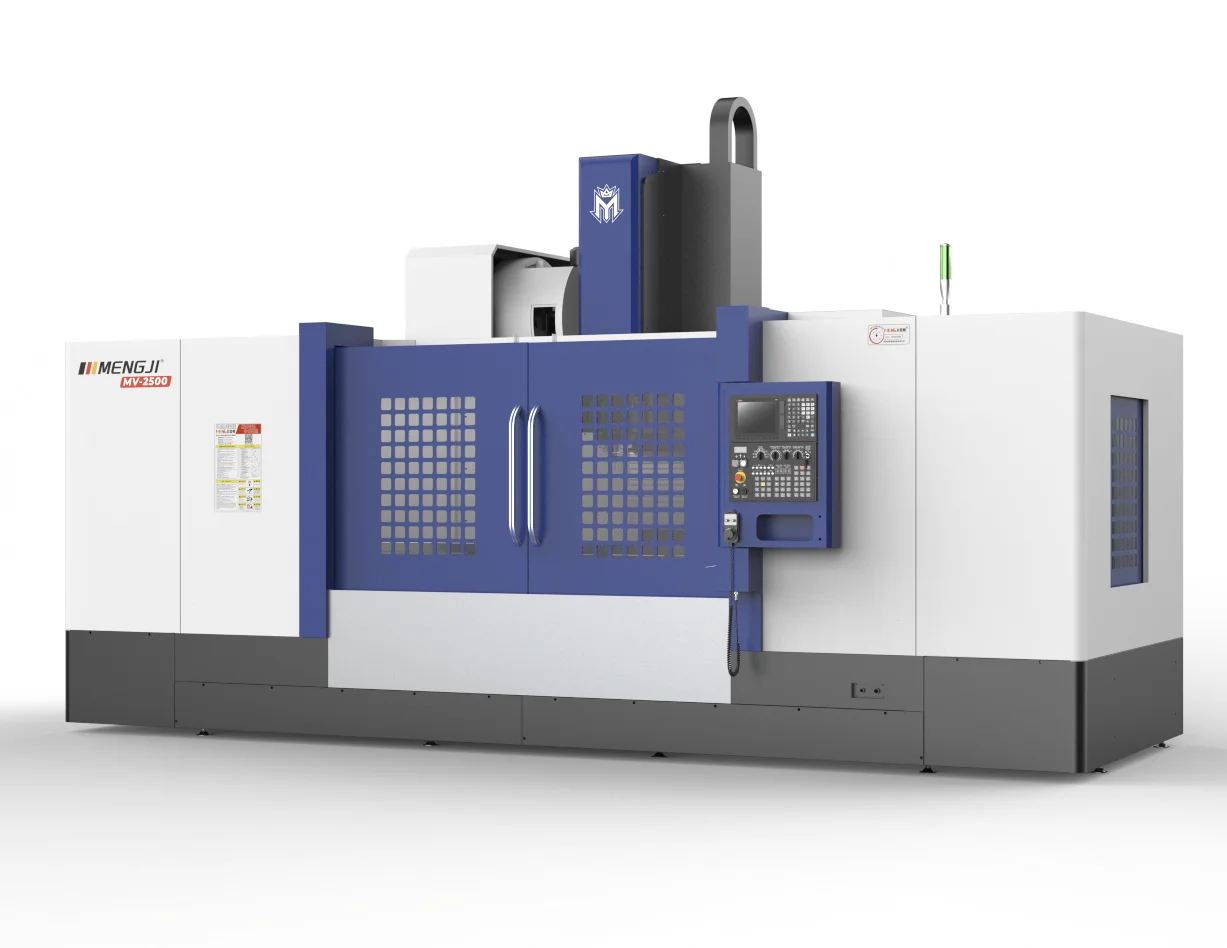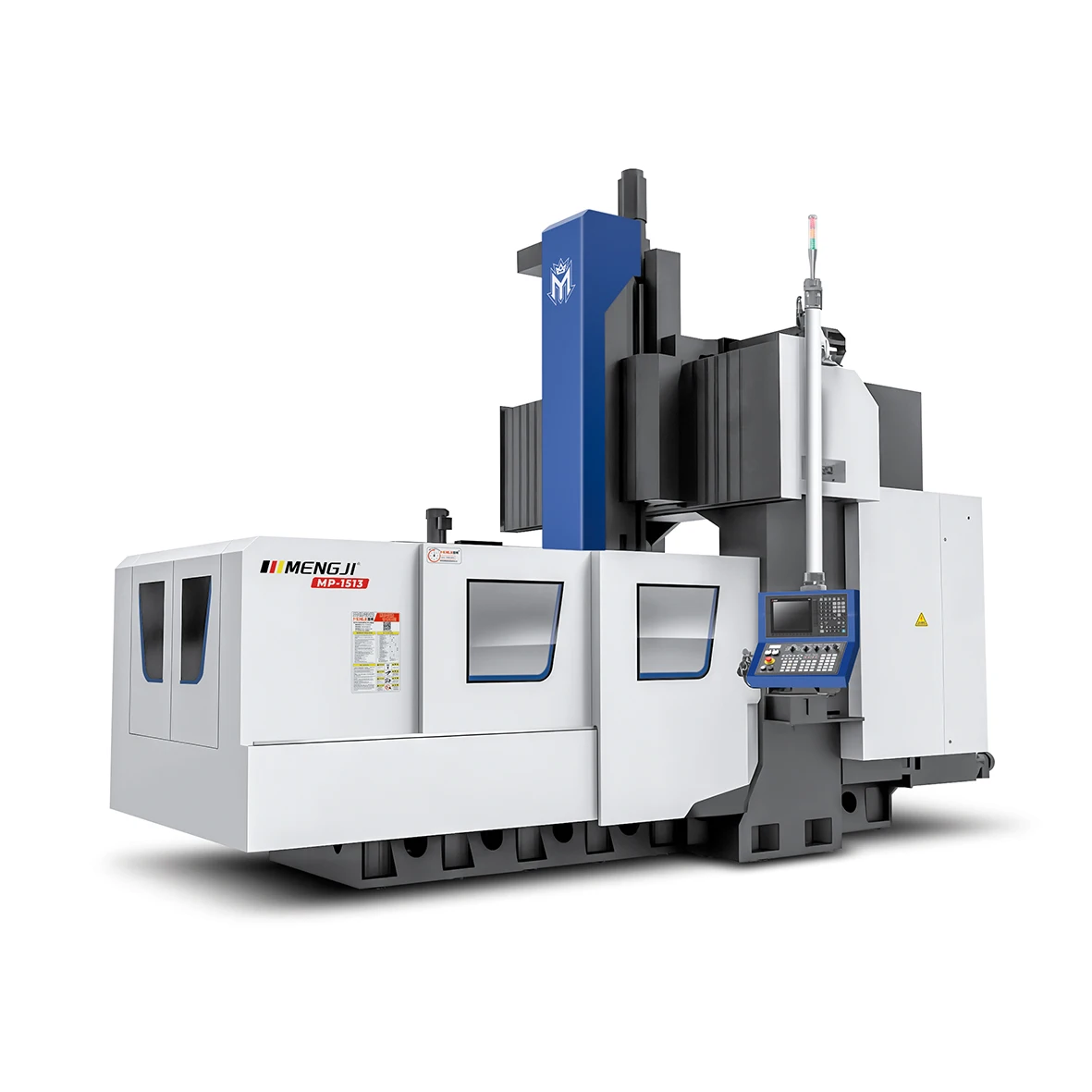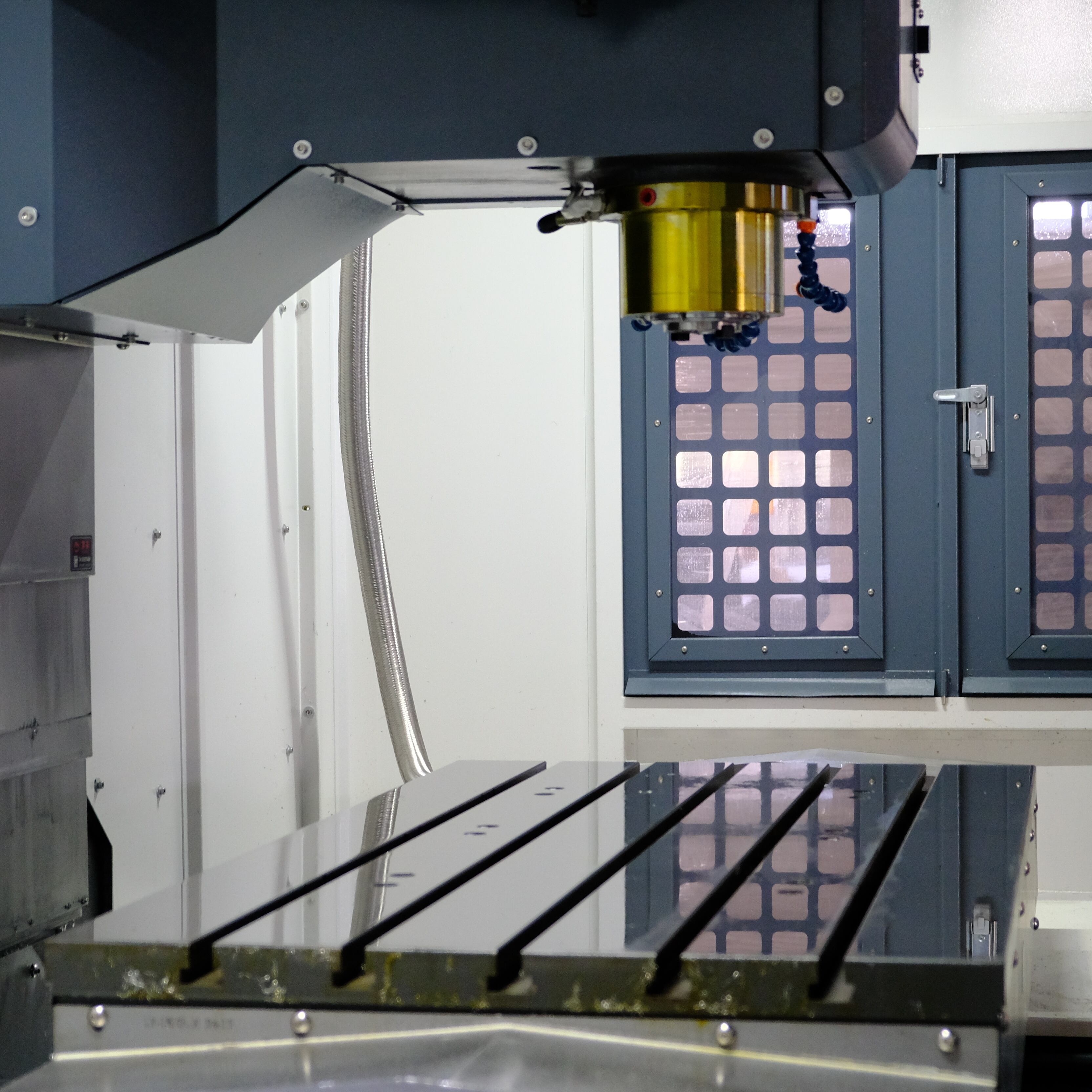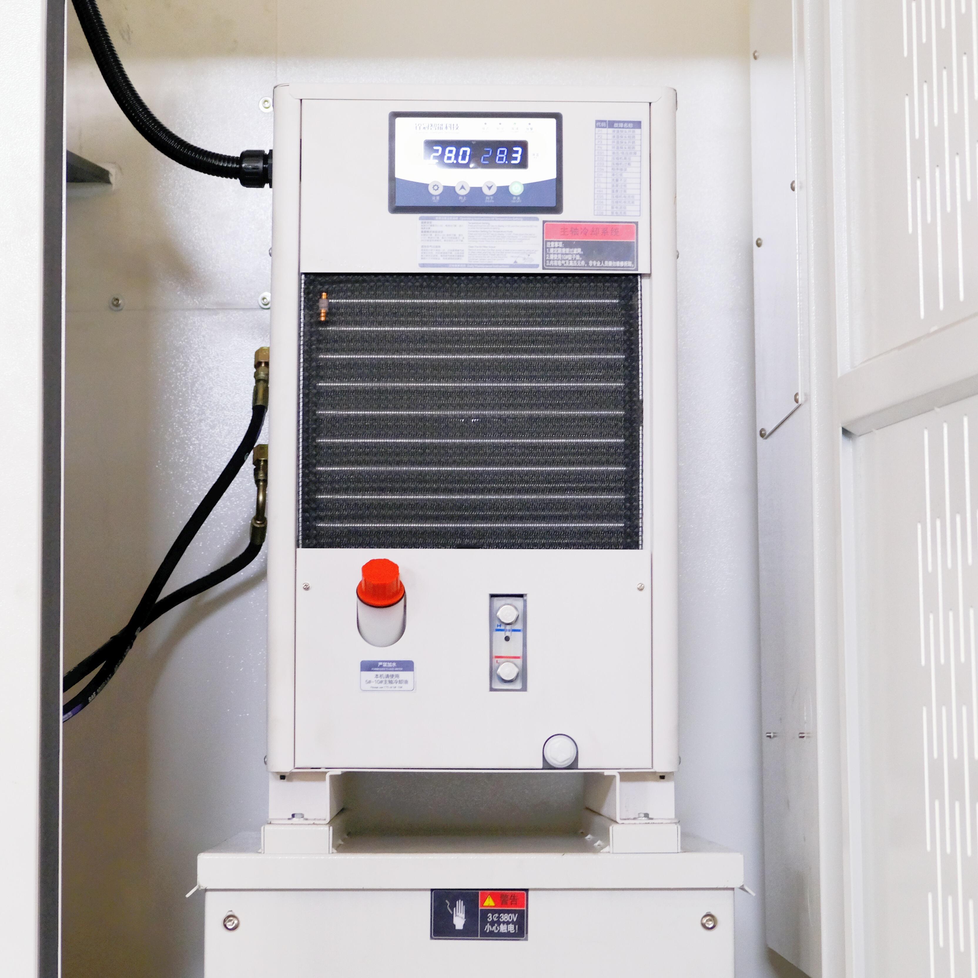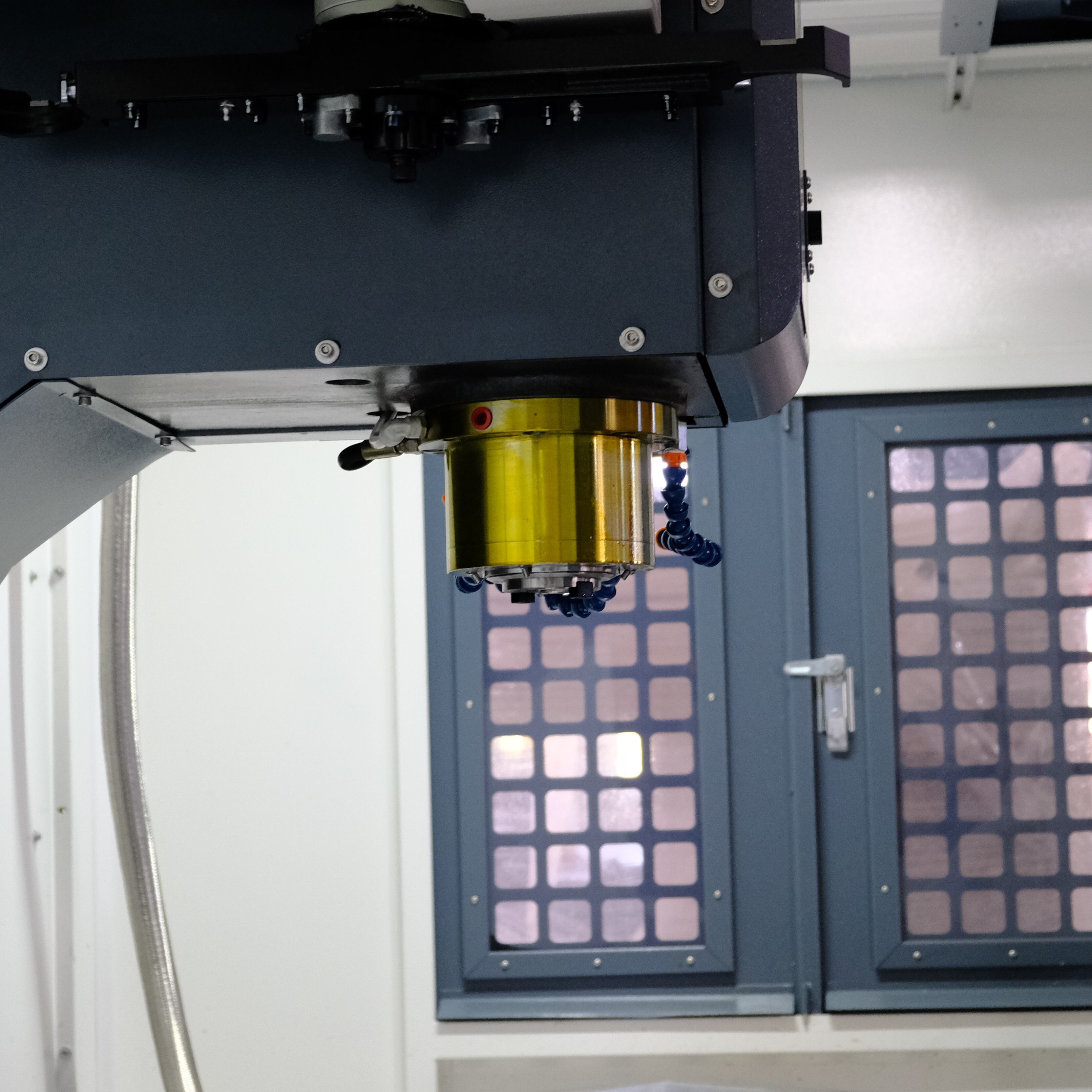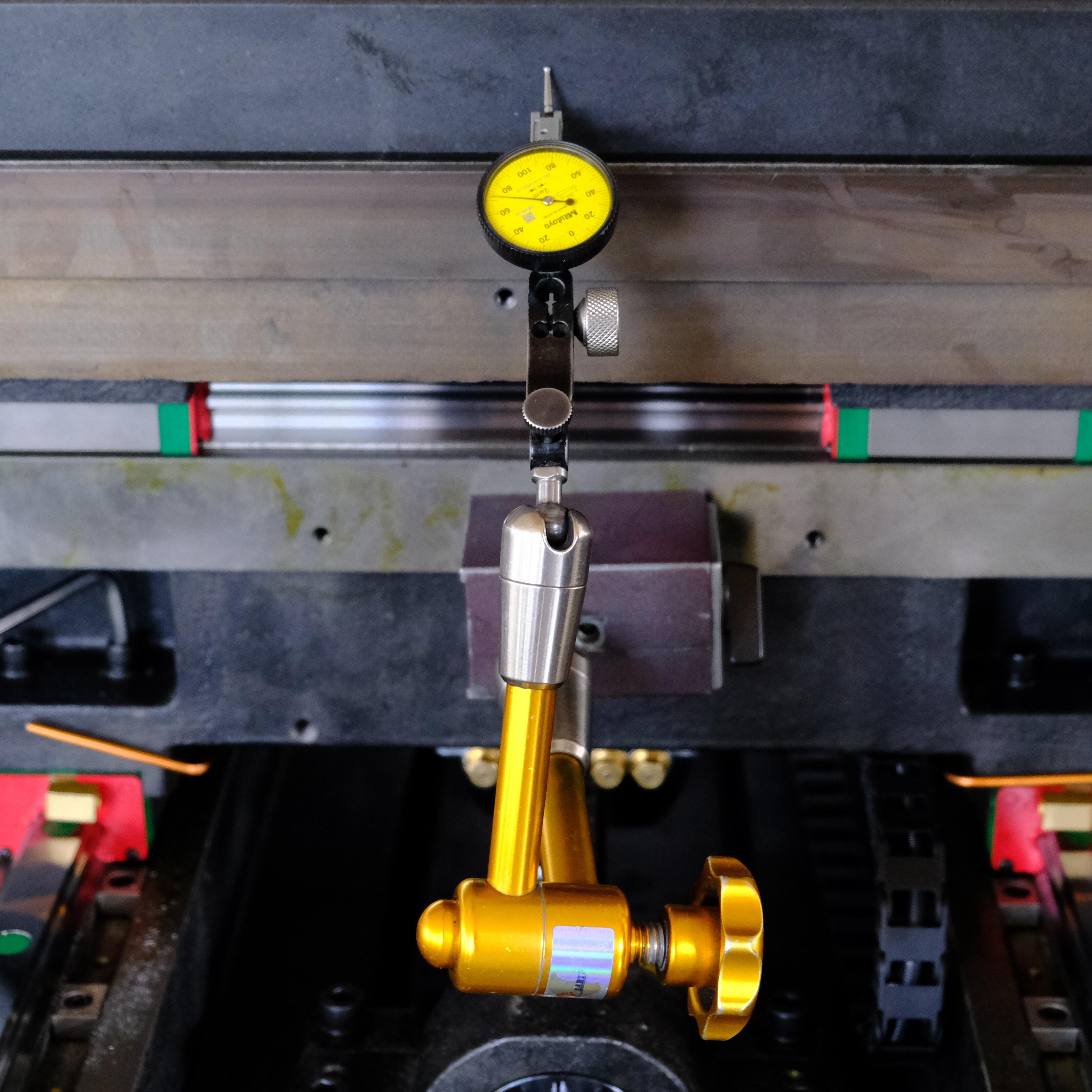
The parts of a CNC mill can be understood by examining its physical and functional anatomy, which combines robust mechanical structures with precision control systems. The major mechanical groups start with the bed, a massive, rigid base that supports all other components. The saddle mounts onto the bed and moves in the Y-axis (front-to-back), while the table, mounted on the saddle, moves in the X-axis (left-to-right) and holds the workpiece via vises or fixtures. The column is a vertical structure fixed to the bed, and the spindle head, which houses the spindle, moves up and down the column on the Z-axis. The spindle itself is the rotating component that holds the cutting tool via a tool holder and is driven by a powerful motor. For automation, an automatic tool changer (ATC) with a tool magazine is present to swap tools as programmed. The drive system consists of servomotors connected to ball screws for each axis, converting electrical energy into precise linear motion. The CNC control system is the nerve center, comprising the control unit (a specialized computer), the operator control panel with a screen and keyboard, and the drive amplifiers that power the motors. This system relies on feedback from rotary encoders on the motors or linear scales on the axes to ensure the actual position matches the commanded position. Additional essential parts include the coolant system, with a pump, tank, and nozzles, to cool the tool and workpiece and flush away chips; the lubrication system for the guideways and ball screws; and the machine enclosure for safety and containment. Understanding these parts provides insight into the machine's capability to perform complex, unattended machining with exceptional accuracy.
Our professional sales team is always ready to assist you.