Structural Integrity and Machine Rigidity Requirements
Frame Design Impact on Thermal Stability and Vibration Damping
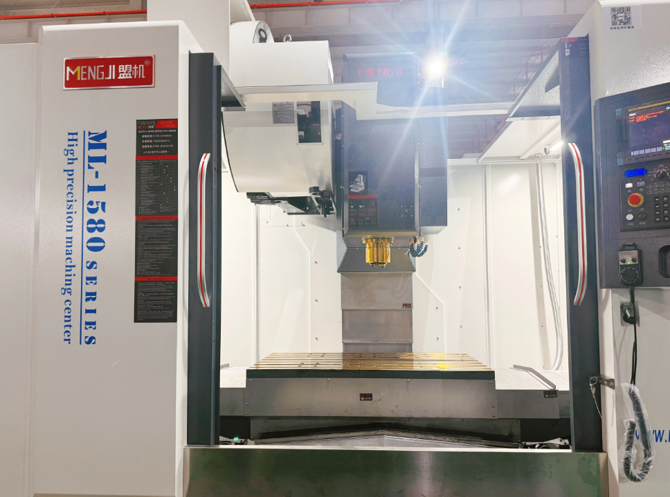
The frame design plays a really important role in keeping Vertical Machining Centers (VMCs) thermally stable and controlling vibrations. When manufacturers use heavy duty cast iron or welded steel for frames, they significantly cut down on thermal distortion during long production runs, which helps keep parts accurate to around plus or minus 0.0005 inches. The latest machines incorporate special ribbing patterns along with internal polymer materials that soak up those annoying harmonic frequencies created by spinning spindles. This actually brings down resonant amplitudes anywhere between 60 to 80 percent compared to older designs. Studies using finite element analysis show that frames with asymmetrical shapes get rid of heat about 40 percent quicker than traditional box-like structures something that matters a lot when working on tight tolerance aerospace parts. And let's not forget the base itself it makes a big difference too. A good base construction reduces chatter during intense cutting sessions, which means tools last roughly 30 percent longer and stops those tiny cracks from forming in precision components.
Enclosure Functionality: Chip Containment, Operator Safety, and Environmental Isolation
Enclosures built for durability actually perform three main roles: containing chips, protecting operators, and isolating from the surrounding environment. The laminated polycarbonate windows can take impacts of around 200 joules without cracking, yet still let workers see what's happening inside. Triple lip seals do a great job at keeping coolant out of those critical guideways where it could cause problems. When it comes to air quality, negative pressure systems grab about 99.7% of tiny particles smaller than 5 microns floating around, which meets OSHA standards for silica exposure. Opening interlocked access doors stops the spindle almost instantly, within just 0.2 seconds, while mist collectors catch roughly 95% of oil mist before it gets exhausted outside. All these components work together to form a kind of sealed environment that keeps things clean during medical device production and helps maintain ISO Class 7 requirements when working with materials that need to be biocompatible.
Foundation and Facility Readiness for Vertical Machining Centers
Concrete Slab Specifications: PSI, Depth, Curing Time, and Anchoring Protocols
For VMC installations, the concrete slab needs to be at least 3000 PSI because vibrations can actually reduce accuracy by more than 0.0005 inches when doing heavy cutting operations. The depth starts around 6 inches for lighter equipment, though it goes up to 12 inches or more for those really heavy machines that weigh several tons. Letting the concrete cure properly takes about 28 days total otherwise there's a risk of tiny cracks forming when the machine is running. When it comes to anchoring, most specs call for epoxy grouted bolts placed no further than 18 inches apart across the entire base area of the machine. After everything gets installed, checking the levelness remains critical too. Industry standards generally accept a deviation of about 0.004 inches per linear foot as acceptable for proper operation.
Shop Layout Optimization: Clearance Zones, Crane Access, and Scalable Integration Paths
It's important to leave at least 36 inches of space on all sides of the VMC for emergencies, chip removal work, and when maintenance is needed. The overhead crane path should line up with where the spindle sits and needs to clear the entire swing area of the tool magazine. For anyone thinking about adding automation like pallet changers, it makes sense to plan for about 150% of what the machine currently takes up space-wise. This extra room comes in handy if they ever need to extend rails later on. To get the most out of workflow efficiency, stage raw materials so they run parallel along the longest direction the machine moves. Doing this cuts down on how long workers spend moving parts around, usually saving somewhere between 20 to 25% of their time.
Power Supply and Electrical Integration for Vertical Machining Centers
Voltage, Phase, Amperage, and Harmonic Mitigation for CNC Spindle and Axis Drives
Vertical machining centers need solid electrical systems behind them if they're going to handle those powerful spindles and fast moving axes. Most shops go with three phase 480 volt power as their standard setup. The amperage requirements scale right along with how much horsepower the spindle has. Take a typical 30 horsepower unit for example it usually needs somewhere between 40 and 50 amps running through those circuits. When it comes to those variable frequency drives we've got to keep harmonic distortion under control. According to IEEE 519-2022 standards, we should stay below 5 percent total harmonic distortion otherwise motors might overheat and cause problems with the control systems. To deal with this issue many facilities install passive filters or invest in active harmonic conditioners for their sensitive equipment. And let's not forget about phase imbalance monitoring either. Keeping an eye on this stuff in real time prevents voltage swings that can mess with positioning accuracy sometimes dropping it by as much as 15 percent when things get really bad.
Pre-Startup Verification: Power-On Sequence, Grounding Validation, and Axis Homing Calibration
It's important to go through a staged power on process before running the machine for the first time. This helps prevent damage caused by sudden surges of electricity when everything starts up at once. Check that the grounding is solid too. Run some resistance tests here, aiming for under half an ohm reading. Good grounding keeps those pesky electromagnetic interferences away from our sensitive control systems. Don't forget about setting up the machine's home position properly either. Getting accurate zero points means we can rely on consistent positioning down to thousandths of a millimeter. When we align all those feedback components like linear and rotary encoders with what the drives expect, it really cuts down on expensive accidents happening when parts move too fast across each other.
Worktable Compatibility and Footprint Efficiency
Getting the right worktable setup means finding a sweet spot between what the machine can handle and how much room we actually have in the shop. Most standard sizes run somewhere between 1200 by 900 millimeters all the way up to 2500 by 1500 mm. These dimensions cover pretty much everything needed for regular industrial parts without wasting too much valuable floor space. When picking out specs, make sure there's enough room on the table not just for the biggest piece but also some extra space around it for tools and fixtures to move freely. Going bigger than necessary eats up precious workshop real estate, something industry research shows costs anywhere from 18% to 22% extra in wasted space. Think ahead about possible expansions too. Some tables come with features like rotating attachments or automatic pallet changers that let us grow our operations without needing a whole new table. The strength of the table matters quite a bit too. If it isn't sturdy enough, vibrations will start messing with our machining accuracy, potentially throwing off measurements by as much as 15 microns. Don't forget to check those numbers again for both the parts themselves and all the supporting equipment like loaders and coolant tanks. We need everything to fit comfortably within the available aisles and under the overhead cranes where they operate.