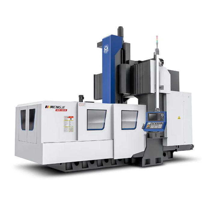
Structural Rigidity and Dynamic Stability in Gantry Machining Centers
Bridge style and double column designs for enhanced rigidity
Modern gantry machining centers typically rely on bridge style or double column setups because they handle cutting forces well, sometimes going beyond 25 kilonewtons without issue. These machines feature what's called a closed loop design with box way guides that spread out stress about 40 percent better compared to old fashioned C frame models. For big jobs like making airplane parts or forging equipment used in power plants, this kind of setup works really well. When running at maximum capacity, these machines keep their shape pretty accurately too, staying aligned within roughly 0.01 millimeters per meter. That means there's less warping when doing intense machining operations on large workpieces.
Material selection and damping characteristics in machine frame integrity
High end gantry machines are now turning to advanced mineral composite casts for their base structures because these materials offer vibration damping that's 3 to 5 times better than regular cast iron. The special polymer concrete used here can soak up around 60 to 80 percent of those annoying harmonic vibrations between 100 and 800 Hz frequencies. This really makes a difference when working with tough stuff like titanium alloys or hardened steel where even small vibrations can ruin precision work. Manufacturers have also started incorporating unique ribbing designs across these frames. These ribs aren't random at all but specifically engineered to target and eliminate certain frequency ranges. As a result, vibration levels stay under control at less than 2 micrometers even during heavy duty rough cutting operations where machines push themselves to their limits.
Load distribution analysis in gantry machining center architecture
According to finite element analysis results, better designed gantries cut down on stress points by around three quarters when compared with older model versions. Modern day systems now feature these dynamic preload adjustments that actually react based on where the axis is positioned and what kind of cutting forces are being applied. The result? Positioning stays consistent at or below five microns throughout the entire eight meter travel range. And let's not forget about those impressive metal removal stats either. These smart load management systems can maintain cutting speeds of about 45 cubic centimeters per minute even when working with tough materials like Inconel 718. At the same time they keep angular accuracy pretty tight too, staying within just one arc minute deviation.
Thermal Stability and Precision Maintenance Under Continuous Operation
Thermal deformation challenges in high speed vertical machining
When running high speed machining operations, the spindle bearings and ball screws can get really hot sometimes reaching over 120 degrees Celsius. There's also a problem with how different parts expand when heated. Cast iron frames expand at around 14 micrometers per meter per degree Celsius while the linear guides expand slightly less at about 11.7 micrometers per meter per degree. This difference builds up over time causing positioning errors that might drift as much as 40 micrometers during the first three hours of operation according to research published by CIRP in 2023. Modern gantry machines tackle this issue by incorporating temperature compensated axis drives. These systems constantly monitor conditions through built in thermal sensors and automatically tweak feed rates based on what they detect, helping maintain accuracy despite the heat buildup.
Active cooling systems and symmetrical design for thermal equilibrium
The best manufacturers out there can hit around 0.5 degrees Celsius thermal stability thanks to balanced machine setups and multiple circuit cooling systems working together. According to research from ITRI in 2024, when they combined three different methods for cooling machines including those fancy fluid controlled spindle chillers, air cooled ball screws, plus linear guides that don't heat up so much, this setup cut down on thermal drift problems by about 82 percent compared to older passive systems. These days most modern CNC machines come equipped with smart software that actually predicts how temperature changes will affect different parts of the machine during operation. This allows them to make adjustments before issues even happen, which is pretty impressive stuff for anyone running high precision manufacturing operations.
Real world performance: Achieving <2µm thermal drift over 8 hours
Field testing under ISO 230 3 standards confirms the effectiveness of hybrid thermal management:
| Cooling Method | Average Drift (8 Hours) | Temperature Variation |
|---|---|---|
| Active Fluid Cooled | 1.5 µm | ±0.8°C |
| Passive Convection | 4.2 µm | ±2.5°C |
| Hybrid System | 0.9 µm | ±0.4°C |
These results demonstrate that integrated thermal control systems can maintain sub micron precision throughout extended production cycles.
Precision Motion Systems: Linear Guides, Ball Screws, and Encoder Feedback
High Resolution Encoders and Real Time Positional Accuracy
Gantry machining centers reach micron level accuracy thanks to optical encoders that can resolve well over a million counts per revolution. These systems work on interferometric principles and are able to spot tiny deviations down to 0.1 microns, which means they can make real time adjustments when running those complicated five axis operations. A recent 2024 industry report showed something pretty interesting too. Machines with encoders above 18 bit resolution cut down scrap rates by about 37 percent when making parts for the aerospace industry from titanium, compared to what happens with machines that have lower resolution capabilities. This kind of precision makes all the difference in high tolerance manufacturing environments.
Preloaded Ball Screws and Anti Backlash Mechanisms for Cutting Precision
Top quality ball screws typically apply preloading forces around 8% or more of their dynamic load capacity just to get rid of that pesky backlash issue. When combined with dual circuit recirculation systems, these components can maintain positioning accuracy down to about plus or minus 2 microns, even when facing pretty hefty cutting loads of around 12 kilonewtons. Many industry leaders have started incorporating temperature compensated nuts into their designs as well. Thermal expansion remains a real headache for machinists, accounting for roughly a quarter of all dimensional errors during extended production runs. These nuts help combat that problem significantly.
Linear Guide Stiffness and Its Impact on Surface Finish Repeatability
Roller type linear guides arranged in four rows and hardened to 60 HRC provide roughly 40 percent improvement in vibration damping compared to regular ball bearing guides. The extra rigidity makes a real difference for surface finish quality, allowing manufacturers to achieve those super smooth Ra values below 0.4 microns across entire production runs without quality drops. Engineering analysis shows that when we adjust the spacing between these guides properly, it cuts down on frame deflection during machining operations. We're talking about around 62% less deflection specifically when working with tool steels that fall within the 55 to 60 HRC hardness range, which is pretty significant for maintaining dimensional accuracy throughout long production cycles.
Emerging Trend: Direct Drive Linear Motors in Next Generation Machining Centers
Direct drive linear motors remove mechanical transmission elements, delivering acceleration beyond 2.5 G and velocity fluctuations under 0.01%. Recent implementations in die and mold applications show contouring speeds 150% faster than ball screw systems, with energy efficiency gains of 18–22%. As contactless drives, they sustain 0.5 µm positioning accuracy for over 20,000 hours without lubrication related wear.
Volumetric Accuracy and Multi Axis Geometric Error Compensation
Gantry machining centers today reach incredible levels of precision at the micron scale thanks to careful error analysis and compensation techniques. Most problems come from what we call position dependent geometric errors (PDGEs) which happen when axes aren't perfectly aligned or materials expand due to heat changes during operation. These PDGE issues typically cause around 60 to 70 percent of all inaccuracies seen in those complicated 5 axis cutting paths. Then there are also position independent geometric errors (PIGEs) that stem from small assembly flaws in the machine itself. According to the latest Machine Tool Accuracy Report from 2023, these PIGEs add another 15 to 20 percent to the overall measurement偏差. Understanding both types helps manufacturers get closer to their target specifications while working within real world constraints.
Understanding position dependent and position independent geometric errors (PDGEs/PIGEs)
As machines move further along their travel path, Position Dependent Geometric Errors tend to grow larger, especially noticeable when there's extended movement along the X axis in those big bridge style gantry systems. When it comes to Position Independent Geometric Errors, these create consistent angular problems that matter a lot in practice. Take a look at what happens with just 25 microns of yaw error at the spindle head end this small mistake can actually lead to around 120 microns worth of position drift when working with tools extending 300 mm from the machine. Today's manufacturers have started adopting interferometry techniques for PDGE calibration work, while ball bar testing remains standard practice for spotting out PIGEs right before final assembly stages. These approaches help ensure machines meet tight tolerances despite inherent mechanical limitations.
Laser interferometer, ball bar, and CMM based validation methods
Three primary techniques ensure volumetric accuracy:
| Method | Purpose | Precision Range |
|---|---|---|
| Laser Interferometer | Linear axis positioning verification | ±0.5 µm/m |
| Ball Bar System | Rotary axis reversal error detection | ±1.5 arc sec |
| CMM Scanning | Complex surface profile matching | 2.5 µm volumetric |
Advanced setups combine these with machine learning algorithms, cutting measurement time by 40% compared to manual processes.
Volumetric error modeling and compensation in five axis CNC systems
Modern CNC controllers correct trajectory errors in real time using differential kinematics models. A 2024 study demonstrated an 82% reduction in 5 axis milling inaccuracies through:
- Real time feedback from linear encoders (X/Y/Z axes)
- Backlash compensation on rotary axes (A/C)
- Predictive models for thermally induced distortions
Bridging the gap between theoretical specs and real world machining performance
While theoretical accuracy can reach below 3 µm, real world variables such as tool deflection and ambient temperature shifts typically limit practical precision to ±5 µm within a 1 m³ working volume. To address this, leading builders now supply "accuracy maps" that detail position specific error compensation values across the entire work envelope.
Integrated Performance: Spindle Dynamics, Vibration Control, and CNC Intelligence
High Speed Spindle Performance and Metal Removal Rate Optimization
Today's gantry machining centers really boost production output thanks to their high speed spindles that run anywhere from 20k to 40k RPM. These machines come with specially designed torque curves for different materials, which makes them much more versatile on the shop floor. The newer motor technology has cut down power losses significantly too. We're talking about only around 8% power loss at full capacity now, compared to those old models where it used to be closer to 15%. This improvement means these machines can keep churning out metal at impressive rates, sometimes hitting up to 1500 cubic centimeters per minute when working with tough steel alloys. And there's something else worth mentioning here: these systems have smart adaptive controls that adjust torque delivery as they sense changes in cutting resistance during operation. What does that mean practically? Better efficiency overall and longer lasting tools before replacement becomes necessary.
Dynamic Balance and Bearing Technologies for Spindle Longevity
The hydrostatic bearing systems equipped with active thermal compensation keep radial runout under 1 micrometer throughout extended operations lasting up to 12 hours straight. These systems rely on dual range vibration sensors that track imbalances across both low frequency ranges (around 0.5G) and higher ones reaching into the 5kHz spectrum, which then prompts automatic changes in rotational speed when needed. After taking apart spindles following roughly 10,000 hours of service time, engineers have found that this method cuts down bearing wear by about two thirds when compared against traditional passive damping approaches commonly used in the industry.
Active and Passive Vibration Damping for Ra <0.4µm Surface Finishes
The inclusion of tuned mass dampers in Z axis carriages helps control those annoying resonant frequencies between 200 to 800 Hz, which is really important when trying to get that smooth finish on parts. Combine this setup with polymer concrete bases that can soak up about 95 percent of all vibration energy, and manufacturers start seeing remarkable results. Surface roughness stays consistent throughout production runs, typically staying within plus or minus 0.02 micrometers even on larger components. Industry tests have shown something pretty impressive too: active magnetic damping solutions settle down much quicker compared to traditional hydraulic systems, cutting settling time by around three fifths according to recent field trials. This kind of performance makes a big difference in shops where precision matters most.
AI Driven CNC Controls Enabling High Speed, Five Axis Toolpath Efficiency
Machine learning algorithms process over 2,500 process parameters to optimize five axis toolpaths, reducing non cutting time by 35% while maintaining 0.005 mm contour accuracy. Real time stiffness mapping allows adaptive feed rate control, preventing tool deflection beyond 3 µm—even when machining thin walled titanium components at feed rates up to 800 mm/min.
Table of Contents
- Structural Rigidity and Dynamic Stability in Gantry Machining Centers
- Thermal Stability and Precision Maintenance Under Continuous Operation
- Precision Motion Systems: Linear Guides, Ball Screws, and Encoder Feedback
-
Volumetric Accuracy and Multi Axis Geometric Error Compensation
- Understanding position dependent and position independent geometric errors (PDGEs/PIGEs)
- Laser interferometer, ball bar, and CMM based validation methods
- Volumetric error modeling and compensation in five axis CNC systems
- Bridging the gap between theoretical specs and real world machining performance
- Integrated Performance: Spindle Dynamics, Vibration Control, and CNC Intelligence